
¿Cómo se puede elegir el dispositivo de protección contra sobretensiones adecuado para proteger los equipos eléctricos y reducir los costes ocultos?
Electrical surges can damage equipment, interrupt production, y increase maintenance costs. Yet choosing the right Surge Protection Device (SPD) is not always easy: confusing specifications lead to selection errors, strict grounding requirements complicate installation, y hidden failures can go unnoticed. Misleading product claims y unclear maintenance responsibilities add further costs. The solution is to select a reliable Surge Protector based on your system requirements, verify its protection performance, y plan for proper installation y maintenance. This guide explains what buyers need to know before purchasing an SPD.
What is a surge protection device?
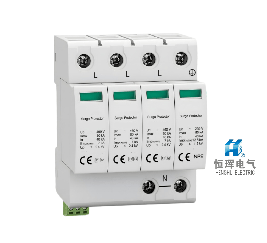
A Surge Protection Device (SPD) is an electrical component that protects equipment from sudden, short-duration voltage spikes, known as transient overvoltages, by limiting the surge voltage and diverting excess current safely through an appropriate discharge path, usually to the grounding system. SPDs help protect electrical installations, industrial control systems, power distribution equipment, and sensitive electronic devices against lightning-induced and switching surges.
Understanding how an SPD works, comparing its types, y checking its technical specifications can help you make a more reliable purchasing decision.
1. What Is a Surge Protection Device, y Why Does Your Electrical System Need One?
A Surge Protection Device (SPD) is designed to reduce the damaging effects of transient overvoltages in electrical systems. These voltage disturbances can occur when lightning strikes nearby, utility networks switch loads, motors start or stop, or inductive equipment generates switching transients.
Although a surge may last only a very short time, its electrical energy can damage sensitive components. Modern facilities increasingly rely on programmable logic controllers, communication equipment, variable frequency drives, monitoring instruments, y digital protection systems. These devices can be vulnerable to voltage disturbances even when the main power supply appears normal.
Why Are Electrical Surges a Serious Risk?
Surges can create several problems for equipment owners y facility operators:
-
Equipment damage: Excessive transient voltage can damage insulation, electronic components, circuit boards, y power supplies.
-
Unexpected downtime: A damaged control system or communication device may interrupt production y delay project delivery.
-
Higher maintenance costs: Repeated failures can increase spare-parts consumption, troubleshooting time, y labor expenses.
-
Reduced equipment lifespan: Repeated electrical stress can gradually weaken insulation y electronic components.
-
Safety and reliability concerns: Surge-related failures may affect protection, monitoring, or control functions in critical installations.
For industrial users, the financial consequences may extend far beyond the replacement cost of an individual component.
How Does an SPD Help Reduce These Risks?
A properly selected Surge Protector limits transient overvoltage y provides a controlled path for surge current. Depending on its design, it may use components such as metal oxide varistors (MOVs), gas discharge tubes (GDTs), or other surge-limiting technologies.
However, an SPD does not eliminate every electrical hazard. It is not a substitute for circuit breakers, residual current protection, overcurrent protection, or a properly designed grounding system.
The most effective protection strategy considers the entire electrical installation, including the incoming power supply, distribution panels, connected equipment, grounding y bonding, y any external signal or communication lines.
For buyers, the goal is not simply to purchase an inexpensive SPD. It is to obtain the right protection level, dependable product quality, and manageable lifecycle costs.
2. How Does a Surge Protection Device Work During a Voltage Surge?
Understanding the operating principle of an SPD helps buyers evaluate product claims y select equipment appropriate for their applications.
Under normal operating conditions, an SPD connected in parallel with a power circuit generally presents a high impedance or otherwise remains inactive, depending on its design. It does not continuously carry the normal load current through its surge-protection element.
When a transient overvoltage occurs, the SPD responds by changing its electrical behavior. It limits the voltage appearing across the protected circuit y provides a path for surge current. When the transient ends, the device returns to its normal operating state if it has not been damaged or reached the end of its service life.
The Main Stages of Surge Protection
1. Normal operation
The SPD remains ready to respond while the electrical system operates within its intended voltage range. Its presence should not interfere with normal power distribution when correctly selected y installed.
2. Detection of a transient
When a surge raises the voltage above the device’s operating threshold, its protective components respond. The actual response depends on the SPD technology, transient waveform, y characteristics of the surge.
3. Voltage limitation and surge-current discharge
The device limits the transient voltage y conducts surge current through its designed discharge path. The grounding y bonding system is essential because it provides the intended route for current in many common protection arrangements.
4. Recovery or disconnection
After the surge subsides, a healthy SPD returns to its normal state. If the device has deteriorated, become thermally damaged, or experienced a severe event, its internal disconnector may isolate it from the circuit.
Which Components Make This Process Possible?
Common SPD technologies include:
-
Metal oxide varistors (MOVs): Voltage-dependent components widely used in low-voltage power SPDs. Their resistance decreases significantly as voltage rises.
-
Gas discharge tubes (GDTs): Components that become conductive when a sufficient voltage initiates gas discharge. They can handle substantial surge currents in suitable designs.
-
Spark gaps: Devices that create a discharge path when a specified voltage condition is reached.
-
Thermal disconnectors: Mechanisms that disconnect deteriorated or overheating protective elements under defined conditions.
-
Status indicators: Visual indicators that help maintenance personnel identify whether a replaceable SPD module remains operational.
Some products combine different technologies to balance response characteristics, energy-handling capability, y voltage protection performance.
Why Does Grounding Matter So Much?
Even a high-quality Surge Protection Device can provide inadequate protection if installed incorrectly. Poor connections, excessive conductor length, unsuitable routing, or inadequate bonding can increase the voltage that appears at the protected equipment during a surge.
For this reason, installation should follow the manufacturer’s instructions y applicable electrical standards. The grounding system, conductor arrangement, upstream overcurrent protection, y SPD connection configuration must all be considered.
A reliable SPD is part of a complete protection system—not an independent solution that can compensate for poor installation.
3. Which Types of Surge Protection Devices Should You Choose for Your Application?
Not all SPDs are designed for the same electrical environment. Choosing the right type depends on the installation location, expected surge exposure, equipment sensitivity, y coordination with other protective devices.
For low-voltage AC power systems, IEC 61643-11 provides a key product standard for surge protective devices connected to low-voltage power systems. Commonly used classifications include Type 1, Type 2, and Type 3, which are selected according to the protection role y test requirements.
Type 1 SPD: Protection Against High-Energy Surge Currents
A Type 1 Surge Protection Device is intended for installation where part of a lightning current may enter the electrical installation, such as at an appropriate service entrance in a building with an external lightning protection system.
Type 1 devices are tested using an impulse current waveform representative of lightning-current stresses. Their performance is commonly described using the Iimp parameter.
Typical applications include:
-
Industrial facilities with external lightning protection systems.
-
Commercial buildings exposed to significant lightning-current risks.
-
Main distribution installations requiring lightning-current discharge capability.
-
Electrical systems designed in accordance with a lightning risk assessment.
A Type 1 SPD should not be selected merely because it has a high current rating. The installation design, earthing arrangement, applicable standards, y required impulse current performance must be evaluated together.
Type 2 SPD: Protection in Distribution Boards
A Type 2 SPD is commonly installed in main or sub-distribution boards to limit transient overvoltages caused by switching operations y residual lightning-induced surges.
It is tested using an 8/20 μs current impulse, y its surge-current performance is commonly specified through parameters such as In y Imax.
Type 2 SPDs are widely used in:
-
Factories y workshops.
-
Commercial buildings y offices.
-
Solar photovoltaic AC distribution systems.
-
Building distribution panels.
-
Industrial automation power supplies.
For many low-voltage installations, Type 2 protection is a central part of the surge protection strategy. Nevertheless, its suitability depends on the expected exposure y the protection already provided upstream.
Type 3 SPD: Protection Near Sensitive Equipment
A Type 3 SPD is designed for coordinated protection closer to sensitive electrical or electronic equipment. It is tested using a combination-wave generator or another specified test arrangement under the applicable standard.
Typical applications include protection near:
-
Computer systems y communication equipment.
-
Electronic control units.
-
Sensitive monitoring devices.
-
Certain industrial automation components.
-
Equipment requiring additional local voltage limitation.
Type 3 protection should generally be coordinated with upstream surge protection. It should not automatically be treated as a replacement for Type 1 or Type 2 protection where those devices are required by the installation design.
How Do Type 1+2 SPDs Fit In?
A Type 1+2 Surge Protection Device combines test characteristics associated with both Type 1 y Type 2 protection. It can simplify protection arrangements in suitable installations by providing lightning-current y general distribution-level surge protection in one device.
However, a combined SPD must still meet the required ratings y coordination requirements. Buyers should check its declared test performance instead of relying only on the product label.
What About DC y Solar PV Surge Protection?
Solar photovoltaic systems have DC circuits that require SPDs designed specifically for their electrical conditions.
A DC Surge Protection Device for PV applications must be compatible with the system’s maximum DC voltage, short-circuit conditions, polarity, grounding arrangement, y expected surge exposure.
For example, a PV installation may require protection on DC strings y AC distribution circuits, as well as appropriate protection for communication lines. Each location requires a suitable device.
Never assume that an AC SPD can be used on a DC circuit. Select a product specifically rated for the circuit type y maximum operating voltage.
4. Which SPD Specifications Should You Check Before Purchasing?
Technical specifications are among the most important factors in SPD purchasing. However, a long datasheet can be difficult to interpret, y selecting a device based on only one impressive number may result in inadequate protection.
The following parameters help buyers compare products more accurately.
1. Maximum Continuous Operating Voltage (Uc)
Uc is the maximum voltage that may be continuously applied to the SPD under the conditions specified by the manufacturer.
The correct value depends on the electrical system’s nominal voltage, earthing arrangement, y connection configuration. For three-phase systems, buyers should confirm whether the device is intended for line-to-line, line-to-neutral, or line-to-earth protection.
If Uc is too low, normal operating conditions or temporary overvoltages may cause unwanted operation or premature deterioration. If it is unnecessarily high, the SPD may provide a higher voltage protection level than desired.
Therefore, Uc should match the actual system requirements, not simply the most common rating shown in a catalogue.
2. Voltage Protection Level (Up)
Up describes the declared voltage-limiting performance of an SPD under specified test conditions.
A lower Up can be desirable because it indicates a lower declared limiting voltage under those conditions. However, the selected device must also have sufficient surge-current capability y be compatible with the installation.
The actual voltage appearing at equipment terminals can be higher than the SPD’s declared Up because of conductor inductance, connection length, y installation arrangement.
Buyers should therefore consider both the device’s rated performance y the voltage withstand capability of the equipment being protected.
3. Nominal Discharge Current (In) y Maximum Discharge Current (Imax)
These parameters are particularly relevant to Type 2 SPDs.
-
In: The nominal discharge current associated with the specified 8/20 μs test.
-
Imax: The maximum discharge current associated with the specified 8/20 μs test, where declared for the device.
A higher current rating can be useful for installations with greater surge exposure, but it does not automatically mean that the SPD is better for every application.
Compare the ratings using the same test waveform y applicable standard. Also check Up, Uc, service-life considerations, y the required protection configuration.
For Type 1 SPDs, Iimp is a key parameter representing the declared impulse current capability under the specified lightning-current test.
4. Respuesta Characteristics y Coordination
SPD technologies respond differently to changing voltage conditions. However, response time alone is not enough to determine real-world protection quality.
A buyer should consider:
-
Declared voltage protection level.
-
Surge-current ratings.
-
Coordination between upstream y downstream SPDs.
-
Compatibility with connected equipment.
-
Manufacturer test documentation.
Proper coordination helps prevent one protective device from carrying an unsuitable share of the surge energy y improves the overall protection arrangement.
5. Short-Circuit Rating y Backup Protection
An SPD must be suitable for the prospective short-circuit current at its installation point y must be installed with the required upstream overcurrent protection.
Check the manufacturer’s specifications for short-circuit current rating, backup fuse or circuit-breaker requirements, and any associated conditional ratings.
Using an unsuitable fuse or circuit breaker can compromise the installation’s safety or interfere with the SPD’s intended operation.
The required arrangement depends on the specific SPD model y local electrical regulations. Buyers should not assume that every SPD can use the same backup protection.
6. Operating Status y Remote Signaling
One common purchasing concern is that SPD degradation may go unnoticed until equipment fails.
Many SPDs include a visual status indicator that shows whether the protective module is operating normally or has been disconnected. Some models also provide a remote signaling contact for connection to a building management system, PLC, or alarm circuit.
These features can help maintenance personnel identify a failed module y schedule replacement.
When purchasing an SPD, ask whether it includes:
-
A clear visual status window.
-
Replaceable protection modules.
-
Remote status contacts, if required.
-
Accessible maintenance instructions.
-
A documented end-of-life indication.
An indicator improves fault visibility, but it does not prove that the SPD can still deliver its original protection performance. Inspection y replacement must follow the manufacturer’s guidance.
5. How Can You Verify SPD Quality y Avoid Hidden Purchasing Costs?
A low purchase price does not always represent the lowest total cost. An SPD that is poorly matched to the installation, difficult to maintain, or supported by incomplete documentation may create additional expenses after delivery.
Check Standards y Prueba Documentation
For low-voltage AC power SPDs, ask for applicable product-standard information, such as IEC 61643-11, where relevant. For PV DC applications, check the applicable DC SPD standard, such as IEC 61643-31.
Request technical datasheets y credible test documentation that identify the actual model y its declared performance. Confirm that the stated parameters match the product being offered.
Be cautious when a quotation lists only a maximum surge-current value without identifying the waveform, test conditions, or other essential specifications.
Evaluate the Complete Product, Not Just the Label
A reliable purchasing assessment should include:
-
Electrical performance: Uc, Up, In, Imax, or Iimp as applicable.
-
Construction quality: Enclosure, terminals, module design, y suitability for the installation environment.
-
Protection coordination: Compatibility with upstream devices y connected equipment.
-
Maintenance support: Replacement modules, status indication, y clear instructions.
-
Technical service: Documentation, troubleshooting guidance, y access to spare parts.
-
Warranty and traceability: Clear model identification, manufacturing information, y defined warranty conditions.
These checks help reduce the risk of choosing a product based on unsupported claims.
Consider Total Cost of Ownership
The total cost of an SPD includes more than its initial purchase price. Depending on the application, it may include installation labor, backup protection, periodic inspection, replacement modules, y downtime caused by unnoticed failure.
For example, an SPD with remote signaling may cost more initially but can be worthwhile in a facility where maintenance staff cannot continuously monitor distribution panels.
Similarly, replaceable modules can simplify maintenance when a protective element reaches the end of its service life.
The right decision depends on the facility’s risk exposure, equipment value, maintenance resources, y operational requirements.
Clarify Responsibility Before Ordering
Buyers should confirm who is responsible for product selection, installation design, grounding arrangements, commissioning, y ongoing maintenance.
A supplier can provide product data y technical recommendations, but the final installation must comply with applicable codes y be evaluated by qualified electrical professionals.
Clear documentation and defined responsibilities help prevent disputes and reduce avoidable lifecycle costs.
6. Where Should Surge Protection Devices Be Installed for the Best Results?
Even a correctly rated SPD may perform poorly if installed in the wrong location or connected incorrectly. The protection strategy should reflect how surge energy can enter the facility y which equipment is most vulnerable.
At the Main Distribution Board
Depending on the lightning risk assessment y installation design, a Type 1 or combined Type 1+2 SPD may be appropriate at the incoming supply.
This location can help manage high-energy surges entering through the electrical service.
At Sub-Distribution Boards
Type 2 SPDs are commonly installed at downstream distribution boards to provide additional protection for circuits supplying machinery, lighting, y other electrical loads.
The number y location of SPDs depend on the system layout, upstream protection, cable lengths, y expected surge exposure.
Near Sensitive Equipment
Where necessary, coordinated Type 3 protection can be installed close to sensitive electronic equipment. This can help limit residual transient voltages at the point of use.
On PV y Communication Circuits
Solar installations may require SPDs on both DC y AC circuits. Communication y signal lines may also need suitable protection if they can introduce surges into control or monitoring equipment.
The selected devices must match the specific circuit y its electrical ratings.
Installation Practices That Matter
Qualified installers should verify:
-
Correct connection configuration y polarity.
-
Suitable conductor size y connection length.
-
Effective grounding y bonding.
-
Required upstream overcurrent protection.
-
Coordination between SPDs.
-
Accessibility for inspection y replacement.
After installation, confirm that the status indicators y remote alarms operate as intended. Inspection frequency should follow the manufacturer’s instructions y the site’s maintenance plan.
Good SPD selection and good installation are equally important.
Conclusion
Choosing the right Surge Protection Device (SPD) requires more than comparing prices or maximum current ratings. Evaluate the application, SPD type, Uc, Up, discharge-current ratings, installation requirements, product documentation, y maintenance features. A properly selected y installed Surge Protector can reduce surge-related equipment damage, improve electrical-system reliability, y help control long-term operating costs.
 Español
 English (UK)
 Bahasa Indonesia
 Tiếng Việt
 Deutsch
 Français
 Português
 Русский